UW Physics
Lecture Demos
Policies & GuidelinesDemonstrationsFull CatalogCourse Demo ListsEquipment Details & ManualsLinks
|
5 - Electricity and Magnetism
| Electrostatics | | Electric Fields And Potential | | Capacitance | | Resistance | | Electromotive Force And Current | | DC Circuits | | Magnetic Materials | | Magnetic Fields And Forces | | Inductance | | Electromagnetic Induction | | AC Circuits | | Semiconductors And Tubes |
5A - Electrostatics5A10 - Producing Static Charge
_th.jpg) | Electrostatic Rods and Cloth (5A10.10)
Glass rods and silk (positive charge), clear acrylic rods and wool (positive charge), red acrylic rods and wool (negative charge), or rubber and fur (negative charge). |
_th.jpg) | Electrophorus (5A10.20)
An aluminum disc with an insulating handle on top of a plastic plate which has been charged by rubbing with a piece of wool. A finger or grounded wire touched to the top of the metal plate removes the induced charge that is the same polarity as the charge on the plate, then the disc is lifted off the plate, leaving the disc charged to a high voltage. This may be repeated many times without recharging the plastic. |
5A20 - Coulomb's Law
| Three Ping Pong Balls
Three aluminum coated and electrically connected ping pong balls hang from a common point on thin wires so that they just touch. The balls are charged with a Wimshurst generator, causing them to repel from each other. A camera is mounted directly above the ping pong balls and shows that the direction of the repulsive force is outwards from the center of the three balls. |
5A22 - Electrostatic Meters_th.jpg) | Electroscope (5A22.10)
An electroscope to show charge. Uses a light to project the shadow onto a translucent glass screen which helps visibility at shallow viewing angles. |
5A30 - Conductors and Insulators_th.jpg) | Conducting and Non-Conducting "T" Terminal on Electroscope (5A30.15)
A large "T" shaped terminal is attached to the electroscope. One arm is made of acrylic and the other arm is aluminum, but both have a metal ball on the end. Touch a charged rod to the ball on each arm to show that only the aluminum arm conducts and charges the electroscope. |
5A40 - Induced Charge_(5A40.10)_th.jpg) | Charge by Induction (Induction Spheres) (5A40.10)
Two metal spheres on insulated stands are touching each other. A charged rod is brought near one of them which induces the opposite charge on the other sphere. While the rod is held close to the first sphere, the other is moved away and touched to the electroscope. |
_th.jpg) | Wood Needle (5A40.30)
A wood 1x2 is placed on a rotating pivot, and will be attracted by either a positively or negatively charged rod due to induction and polarization of the water molecules within the wood. |
_th.jpg) | Metal Rod on Pivot (5A40.35)
An aluminum rod on a rotating stand will be attracted to a charged rod of either polarity due to induced charge in the conductor. |
| Deflection of a Water Stream (5A40.40)
A charged rod deflects drops of water. Note: This is hard to see in a large class. |
_th.jpg) | Kelvin Water Dropper (5A40.70)
An unusual induction machine in which dripping water acts as the carrier for charge buildup in two metal cans. When a sufficiently high voltage is reached, the cans discharge through a small fluorescent bulb. Note: This is hard to see in a large class. |
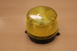
5A50 - Electrostatic Machines_th.jpg) | Wimshurst Machine (5A50.10)
A hand cranked generator produces sparks in the hundred kilovolt range; in principle a continuously operating electrophorus (see 5A10.20). |
| Toepler-Holtz Machine (5A50.15)
Status: Unavailable
Large 300 kV discharges from this antique generator (circa 1895) are very impressive, but give us a few hours notice in order to pre-charge it beforehand. Specific demos include: Lightning Rod (5B30.30), Point and Candle (5B30.40), Pinwheel (5B30.50). Caution: Crank slowly! Note: Needs repairs and is out of service. |
_th.jpg) | Van de Graaff Generator (5A50.30)
A small Van de Graaff generator and a discharge wand. The generator without paper streamers will produce larger sparks than the generator with paper streamers (see 5B10.15). |
5B - Electric Fields And Potential5B10 - Electric Field_th.jpg) | Van de Graaff With Streamers (5B10.15)
A Van de Graaff generator with paper streamers taped to the dome shows the radial shape of the electric field produced by the generator. Can also show the distortion of the field due to the introduction of a grounded metal rod. Note: This works much more reliably than getting hair to stand up. |
| Van de Graaff with Jumping Pie Pans (5B10.25)
A stack of Aluminum pie pans will jump off the Van de Graaff Generator when charged. |
_th.jpg) | Bouncing Ping Pong Balls (5B10.30)
A variation of Franklin's Bells. Aluminum coated ping pong balls bounce up and down between two charged metal plates due to electrostatic forces on the balls. Also shows basic charge transfer. Note: This uses the same setup at the Millikan Oil Drop Analog. |
_th.jpg) | Grass Seed Electric Field (5B10.40)
Electrodes of different shapes are placed in a transparent dish filled with mineral oil and a small amount of grass seed (which contains water). A Wimshurst machine is connected to the terminals and the electric field applies a force on the dipole moment of the water molecules in the grass seed. The seed will then move within the oil and bceome aligned with the electric field produced by the generator. |
5B20 - Gauss' Law | Gaussian Surfaces (Show & Tell)
Show and tell items of various geometries for point, line, and plane charge distributions. |
_th.jpg) | Faraday Ice Pail (5B20.10)
Shows that charge resides only on the outside of a hollow conductor. A metal trash can is charged using a Wimshurst machine, then the charge distribution on the can is investigated using a metal ball on an insulating rod. |
| Faraday Ice Pails on Two Electroscopes (5B20.15)
Two Faraday Ice Pails sit on individual electroscopes. One Ice Pail is charged. A conductive sphere or pith ball is used to transfer half the charge from the outside of one pail to the outside of the other. Both pails are then discharged and reset. Then the pith ball is used to transfer all of the charge from outside of the first pail to the inside of the second. |
_th.jpg) | Faraday Cage (5B20.30)
A large mesh wire cage fits over the electroscope, shielding it from outside electric fields. A high voltage source (a charged acrylic rod) brought near the cage will not deflect the electroscope. |
_th.jpg) | Radio in a Faraday Cage (5B20.35)
A small AM radio is placed in a copper wire mesh cage. Note: The lecture halls themselves sometimes act as large Faraday cages and block all radio transmissions. |
5B30 - Electrostatic Potential
| Toepler-Holtz - Lightning Rod (5B30.30)
Status: Unavailable
A model house with a conductor in the chimney is placed on the Toepler-Holtz machine. One electrode of the machine connects to the chimney, the other to a "cloud" suspended directly above the chimney. When the machine is cranked, impressive sparks between cloud and chimney simulate lightning bolts striking the house. A sharp pointed lightning rod (which is electrically connected to the chimney) is then pushed up out of the top of the house, and the resulting corona discharge stops the lightning immediately. |
_th.jpg) | Van de Graaff and Discharge Wand (5B30.35)
A grounded wand with a round bulb on one end and a sharp point on the other is brought near a charged Van de Graaff. The bulb end draws out impressive sparks, while the pointed end produces only corona discharge. |
| Toepler-Holtz - Point and Candle (5B30.40)
Status: Unavailable
A burning candle brought near a sharp point attached to the Toepler-Holtz machine is nearly blown out due to the electrostatic repulsion on the ions in the flame and the coronal wind from the point. By comparison, holding the candle near the large ball electrode to which the point is attached produces a much smaller effect. |
| Toepler-Holtz - Pinwheel (5B30.50)
Status: Unavailable
A pinwheel with sharp points at the ends of the arms is mounted so as to spin horizontally on one of the electrodes of the Toepler-Holtz machine. When the machine is cranked, the corona discharge from the points causes the pinwheel to spin. |
5C - Capacitance5C10 - Capacitors | Sample Capacitors (5C10.10)
Show and tell capacitors of many types and sizes. |
_th.jpg) | Parallel Plate Capacitor (Variable Separation) (5C10.20)
Two parallel circular metal plates which form a capacitor are supported so that the distance between them can be varied. The plates are connected to an electrostatic voltmeter and charged. As the separation varies, the changing voltage between the plates is reflected in the reading on the voltmeter. See also Parallel Plate Capacitor with Dielectrics (5C20.10). |
| Battery and Separable Capacitor (5C10.21)
A parallel plate capacitor with its plates separated by a thin mica sheet is hooked to the electroscope and charged with a 90 V. battery. The plates are pulled apart, and the decrease in capacitance raises the voltage enough to deflect the electroscope. |
_th.jpg) | Tuning Capacitor (Variable Area) (5C10.35)
Similar to the Parallel Plate Capacitor (5C10.20), but this is a large version of the tuning capacitor used in AM radios, in which the area (overlap) between the plates can be changed. |
5C20 - Dielectrics
_th.jpg) | Force on a Dielectric (5C20.20)
Dielectrophoresis due to a non-uniform electric field at the edge of a parallel plate capacitor. A circular plastic disk on the end of a pivoting arm is balanced between and slightly above the plates of a large parallel plate capacitor. As the capacitor is charged, the force on the dielectric pulls it down between the plates. |
_th.jpg) | Dissectable Leyden Jar (5C20.30)
A Leyden jar with removeable inner and outer conductors is charged with a Wimshurst machine then discharged with a large spark. The Leyden jar is charged again, then disassembled by removing the inner and outer conductors. These can be touched together, grounded, etc., and no sparks are seen. However, if the Leyden jar is now reassembled and discharged, the spark will be almost as large as the original spark. Note: Please see us beforehand about technique. |
5C30 - Energy Stored in a Capacitor | Leyden Jars on a Wimshurst Machine (5C30.10)
A Wimshurst machine is first run without the Leyden jars connected, and frequent but weak sparks are observed. The Leyden jars are then connected, and the discharges become less frequent but much more powerful. |
_th.jpg) | Exploding Capacitor (Show & Tell Only) (5C30.20)
Status: Unavailable
Three 1500 mF capacitors connected in parallel and rated for 400 volts. A shorting bar shows the stored energy could melt and vaporize metals. This configuration is no longer used or charged due to safety concerns. |
| Charge vs. Voltage (5C30.37)
A small capacitor is charged at 1.5V, then discharged through a projection ballistic galvanometer, the amount of deflection of the galvanometer giving an indication of the charge the capacitor held. The same capacitor is then charged to 3V, and the deflection of the galvanometer upon discharge is approximately doubled. |
| Generator and Capacitor (5C30.38)
A hand cranked (Genecon) generator charges a 1 Farad capacitor. When the handle is released, the generator is now a motor powered by the capacitor. Will the handle rotate in the same direction as when charging the capacitor? Or will the handle rotate in the opposite direction? NOTE: See also Genecon Generator and Inductor (5K40.80). |
_th.jpg) | Series and Parallel Capacitors (5C30.42)
Two capacitors mounted on a board which can be used individually, in series, or in parallel. After a combination has been charged to 1.5 V, it is discharged through a projection ballistic galvanometer, and the amount of charge the combination held is reflected in the displacement in the galvanometer. Note: Capacitance of each can vary by +/- 20% so the parallel capactitance is the sum of the two and not necessarily twice either individual capacitance. |
5D - Resistance5D10 - Resistance Characteristics | Sample Resistors (5D10.10)
Various types, values, and power ratings. |
_th.jpg) | Resistance Wires (5D10.20)
One board containing five wires of different lengths, areas, and materials. Each of the wires is hooked in turn across a battery and the current through the wire is shown on a large meter. The dependence of resistance on length, area, and composition of the wire can be shown. See also Ohm's Law (5F10.10) and Series and Parallel Resistance (5F20.55). |
5D20 - Resistivity and Temperature | Coil with Lamp in Liquid Nitrogen (5D20.10)
A lamp in series with a resistance coil doesn’t glow at room temperature. When the coil is submerged in liquid nitrogen, its resistance decreases and the bulb lights brightly. |
| Heated Wire with Lamp (5D20.20)
A resistance wire in series with a small lamp and an ammeter is heated by a gas flame. The resistance of the wire increases with rising temperature, causing the current to decrease and the lamp to dim. |
5D30 - Conduction in Solutions | Conductivity of Solutions (5D30.10)
A probe consisting of two metal prongs with 110 V between them is dipped into various liquids, solutions, etc. If the liquid conducts, current flows and lights a bulb. |
| Glowing Pickle (5D30.30)
Apply 110 VAC across a pickle and it lights at one end. Note: This demo will stink up the whole room! |
5D40 - Conduction in Gases_th.jpg) | Jacob's Ladder (5D40.10)
A classic electrical display often seen in the background of mad scientist B movies. Two long vertical electrodes are close together at the bottom, but separate gradually towards the top. 15,000 Volts from a transformer starts an arc at the bottom. Since the voltage is AC the arc breaks as the voltage decreases; the ionized air that was heated during the arc rises while the arc is off. When the AC voltage again becomes high enough to strike an arc, it goes through the ionized air that has risen above the point of the previous arc. The process continues until the arc reaches the top of the electrodes, where it breaks off and reforms at the bottom to begin the cycle again. |
_th.jpg) | Neon Lamp (5D40.50)
A neon lamp does not conduct below 80 V, but passes current easily above that voltage, and will continue to carry current down to about 60 volts once the current has been started. |
| X-ray Ionization (5D40.80)
Discharge an electroscope with X-rays. |
5E - Electromotive Force And Current5E20 - Electrolysis_th.jpg) | Electrolysis of Water (5E20.10)
Status: Unavailable
DC through slightly acidic water produces hydrogen and oxygen at the electrodes. Matches are provided to ignite the Hydrogen. |
5E30 - Plating | Copper Electroplating (5E30.20)
DC and a copper sulfate bath are used to electroplate copper onto a carbon electrode. |
5E40 - Cells and Batteries | Internal Resistance of Batteries (5E40.75)
Two lead acid batteries, one new and one old, are individually connected to a voltmeter and a switched light bulb. The new battery will have a minimal voltage drop when the bulb is switched on (bright). The old battery has a large internal resistance and will show a substantial voltage drop when connected to a light bulb (dim). |
5E50 - Thermoelectricity | Thermocouple (5E50.10)
Current registers on a milliammeter when this large twisted wire thermocouple junction is heated in a flame. |
| Thermoelectric Magnet (5E50.30)
Heat and cool opposite sides of a large thermocouple. Suspend a large weight from an electromagnet powered by the thermoelectric current. |
| Thermoelectric Pinwheel.
A small pinwheel is powered by a Peltier Junction whose terminals are placed in hot and cold water baths. Swap the water baths and the pinwheel will reverse direction. |
5E60 - Piezoelectricity | Piezoelectric Sparker (5E60.20)
A piezo crystal sparker that can be used to charge an electroscope. |
| Piezoelectric Lighter with Neon Lamp (5E60.21)
The piezo element in a modified fire starter develops sufficient voltage to flash a neon lamp. |
5F - DC Circuits5F10 - Ohm's Law_th.jpg) | Ohm's Law (5F10.10)
Uses the Resistance Wires (5D10.20) board described above, but in this demo the voltage is also varied. |
5F15 - Power and Energy | Voltage and Current in House Lines (5F15.40)
Lamps and heating elements are wired in parallel to 120 VAC. The voltage and current are shown on large multimeters. As each element is switched into the circuit, the current and total power increases. Circuit breakers and old fashioned fuse wire are used to protect the “house.” When these safety features are bypassed, pieces of paper on the wiring will catch on fire. |
_th.jpg) | I^2R Losses (5F15.45)
Nichrome, iron, and copper wires are wired in series with a Variac. A small paper rider is wrapped around each wire. As the voltage is increased, the wires begin to heat up in order of decreasing resistance. Although the current is the same for all wires, the wire with the biggest resistance (nichrome) heats up first and burns its paper rider. Increasing the voltage (and thus the current) further makes the iron wire burn its paper rider and makes the nichrome glow red-hot. The copper wire barely gets warm. |
5F20 - Circuit Analysis | Sum of IR Drops (Kirchoff's Voltage Law) (5F20.10)
Three large variable resistors are wired in series with a battery. The voltage drop across each resistor is measured with a voltmeter, and the sum of them equals the battery voltage. |
| Conservation of Current (Kirchoff's Current Law) (5F20.16)
A two loop DC circuit containing a battery and three variable resistors. Three ammeters measure the current entering a node and the currents in the two loops. |
| Slide Wire Potentiometer (5F20.30)
Highly accurate voltage measuring device. |
_th.jpg) | Wheatstone Bridge (5F20.40)
Measure resistance by balancing voltage drops over two different paths, one of which includes the resistor to be measured. Three types are available: (1) With Lamps to show the principle but not make actual measurements, (2) With a sliding wire to make actual measurements, and (3) A commercial bridge as a show-and-tell item. |
| Series and Parallel Light Bulbs (5F20.50)
Two sets of three light bulbs, one wired in parallel and the other in series, will clearly show the different current in the two circuits by the relative brightness of the bulbs. |
_th.jpg) | Series and Parallel Resistance (5F20.55)
Two identical resistance wires on a board are connected to a battery, either individually, in series, or in parallel. The current for the different configurations is measured with a large meter. |
| Resistor Cube
Twelve identical resistors are soldered together to form the edges of a cube, whose resistance can be measured across an edge, a face, or across the entire cube from corner to corner. |
5F30 - RC Circuits | RC Circuit (5F30.20)
An oscilloscope plots the voltage across a capacitor (or the resistor) in a RC circuit. |
| RC Circuit Analog
A flat disc on the end of a spring is submerged in a large glass jar of water. Pull up suddenly on the end of the spring and the disc will rise in the water, quickly at first then slowly as it approaches equilibrium, similar to a RC circuit. The spring is analogous to the capacitor - pulling on it suddenly is the same as applying a sudden voltage. The resistance of the water to the motion of the disc is the analogue of the electrical resistance in the circuit. The distance that the disc moves is the analogue of capacitor charge. |
_th.jpg) | Relaxation Oscillator (5F30.60)
A capacitor, resistor, and DC power supply are wired in series, with a neon bulb in parallel with the capacitor. The capacitor charges to about 80 V (the breakdown voltage of the neon bulb), then discharges through the bulb and begins the cycle again. The capacitor voltage can be plotted on an oscilloscope. |
 | Emergency Flasher
A commercial emergency flasher uses a 9V battery to flash a neon lamp at approximately 2 Hz. The battery voltage is stepped up internally to provide the 600 Volts needed to flash the tube. |
5F40 - Instruments | Loading by a Voltmeter of Insufficient Resistance (5F40.21)
Voltages in a simple series circuit are measured first with a voltmeter with a high input impedance, then are dragged down by simultaneously using a voltmeter with a low input impedance. Another variation is to use one voltmeter to measure the input impedence of a second voltmeter. |
5G - Magnetic Materials5G10 - Magnets | Lodestone (5G10.16)
Magnetite, a naturally occurring magnetic mineral. Color coded with North and South poles. |
| Broken Magnets (5G10.20)
A broken bar magnet held together by its own magnetism acts as a single magnet when whole. It can be pulled apart into two or more pieces and their fields traced with compasses and/or iron filings to show that each piece is also a complete magnet. |
5G20 - Magnetic Domains and Magnetization | Barkhausen Effect (5G20.10)
A soft iron core is surrounded by a pickup coil. Bringing a permanent magnet nearby causes domains in the iron to become aligned, which is picked up as white noise by the coil and amplified into a speaker. |
| Magnetic Domain Model (5G20.30)
A plastic plate holds small bar magnets on bearings which simulate domains. They line up with one another, flip in the presence of an external field, etc. Use with the document camera. |
| Electromagnet with 1.5 Volt Battery (5G20.70)
A small electromagnet powered by a 1.5V battery that can hold several kilograms. |
| Big Electromagnet (5G20.72)
A huge coil carries about 25 Amps and produces a very strong field; will attract nails, etc. that are brought near. A nail on a string allows the shape of the field to be probed, and the removeable iron core concentrates the magnetic flux. Note: See also Lamp in Parallel with a Solenoid (5J20.20). |
5G30 - Paramagnetism and Diamagnetism | Paramagnetism and Diamagnetism (5G30.15)
Paramagnetism: Test tubes of manganese chloride and copper sulfate are balanced on the ends of a rotating bar. A strong horseshoe magnet brought nearby will attract both materials towards the magnet. Diamagnetism: A similar rotating configuration with blocks of bismuth will be repelled by the magnet. |
5G40 - Hysteresis | Hysteresis Waste Heat (5G40.50)
A small amount of water is contained in the secondary coil of a transformer. Waste heat from eddy currents and magnetic hysteresis boils the water. |
5G50 - Temperature and Magnetism | Heated Canadian Nickel (5G50.15)
Nickel (Curie temp: 358 C) is ferromagnetic at room temperature and paramagnetic when heated with a gas torch. A Canadian nickel hangs from a wire and is initially suspended by a strong magnet. After heating, the nickel falls away from the magnet. |
| Curie Temperature Wheel (5G50.20)
A rotating wheel (made of 70% iron and 30% nickel) passes through the poles of a magnet, and has a Curie temperature slightly above room temperature. A spot on the wheel directly above the magnet is heated with a focused carbon arc lamp and becomes paramagnetic. The ferromagnetic region directly below the magnet is then drawn upwards and the wheel begins to rotate. By the time the first hot spot makes a complete revolution, it has cooled enough that the rotation is continuous. |
| Dysprosium with Liquid Nitrogen (5G50.25)
Dysprosium (Curie temp: -188 C) becomes ferromagnetic when cooled with liquid nitrogen. A piece of dysprosium hangs freely at room temperature. After cooling it is attracted to a strong magnet, but falls away as it warms up. |
| Meissner Effect (Superconductor Levitation) (5G50.50)
A YBCO superconducting disc (Yttrium Barium Copper Oxide) is cooled with liquid nitrogen and will then cause a small permanent magnet to levitate above the disc. |
5H - Magnetic Fields And Forces5H10 - Magnetic Fields | Compass (5H10.11)
A large compass that reacts to Earth's magnetic field. |
| Dip Needle (5H10.15)
The large compass above may be oriented vertically along a North-South line to serve as a large dip needle to show the inclination of Earth's magnetic field. |
| Oersted's Needle (5H10.20)
A compass is brought near a wire carrying a large current. Works best using the overhead projector 5H10.30. |
| Magnetic Fields Around Magnets (5H10.30)
Iron filings on a plastic shield are placed on the overhead projector and used to show the shape of the field around bar and horeshoe magnets. Small transparent compasses are also available to show the sense of the field. |
5H15 - Fields and Currents | Magnetic Fields Around Conductors (5H15.10)
Wires in various configurations on transparent boards carry a large current; board is placed on overhead and sprinkled with iron filings to show shape of the field. Small transparent compasses can be used to show the sense of the field. Same setup at Magnetic Fields around Magnets (5H10.30) and Oersted’s Needle (5H10.20) |
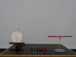
5H20 - Forces on Magnets | Magnetic Attraction and Repulsion (Bar Magnets on Pivot) (5H20.10)
Bar magnets on a pivoting stand show attraction and repulsion. Note: See also Electrostatic Attraction and Repulsion (5A20.10). |
| Levitron (5H20.22)
A spinning magnetic top that levitates above a large permanent magnet. It takes some adjustment to get it working right, so please give us lots of notice and be prepared to practice beforehand. |
5H25 - Magnet/Electromagnet Interactions | Hanging Solenoid and Bar Magnet (5H25.10)
A solenoid hangs from a ring stand and is free to interact with a bar magnet. There’s no interaction when the current is off, a weak interactions without the iron core, and a strong interaction with the iron core. |
5H30 - Force on Moving Charges | Electrostatic Deflection of an Electron Beam (Oscilloscope)
An external DC power supply is connected to the vertical plates of the open oscilloscope. Changing the applied voltage changes the vertical deflection of the electron beam. |
| Electrostatic Deflection of an Electron Beam (Crooke's Tube)
The horizontal electron beam in a Crooke's tube is deflected vertically by a perpendicular electric potential from a large power supply. |
| Magnetic Deflection of an Electron Beam (Oscilloscope) (5H30.10)
An electron beam is deflected by the field from a bar magnet. Note: The Crooke’s tube is the better demo. |
| Magnetic Deflection of an Electron Beam (Crooke's Tube) (5H30.15)
An electron beam is deflected by the field from a bar magnet. |
| Fine Beam Tube (5H30.20)
An electron beam in an evacuated glass sphere is bent into a circle by the magnetic field from a pair of large Helmholtz coils. Both the accelerating potential and coil current can be changed. |
| Thomson's E/M Experiment
An electron beam in an open oscilloscope is vertically deflected by an electric field, then by a transverse magnetic field which balances the electric field and reduces the deflection to zero. Ratio of electron charge to mass could then be calculated from the values for deflection and field intensities, but the demo is usually only done qualitatively. |
| Ion Motor (Force on Ions) (5H30.55)
Cork particles floating in a solution of copper sulfate in a circular container will rotate when current is passed through the solution in the presence of a magnetic field. Reverse either the current or the magnets to reverse the rotation of the solution and cork. Remove the magnets and the solution and cork will slowly come to rest. |
5H40 - Force on Current in Wires | Pinch Wires (5H40.20)
Parallel hanging wires are either attracted or repelled by one another, depending on the direction of currents in the wires. Three different configurations. |
| Jumping Wire (5H40.30)
A single thick wire passes between the poles of a powerful horseshoe magnet. When a heavy duty DC power supply is turned on, the wire jumps out of the field. |
| Barlow's Wheel (Video Only) (5H40.50)
A disc of aluminum on bearings whose bottom half passes between the poles of a powerful magnet. A large DC current runs from the center to the bottom point of the disk, and the force on the electrons flowing through the magnetic field causes the disk to rotate. Note: This demo is no longer in service due to exposed mercury involved in its operation. |
| Ampere's Frame (Video Only) (5H40.70)
A large DC current flows through a square wire frame. A magnet brought near the frame will cause it to rotate. Note: This demo is no longer in service due to exposed mercury involved in its operation. |
5H50 - Torques on Coils | D'Arsonval Meter (Model Galvanometer) (5H50.10)
A large open model of an galvanometer. A large coil on spring mounted bearings twists in the field from a permanent magnet when current flows in the coil. |
5J - Inductance5J10 - Self Inductance | Sample Inductors (5J10.10)
Various commercial and homemade coils. |
5J20 - LR Circuits | RL Circuit (5J20.10)
A large inductor in series with a resistor, a battery and a switch. When the switch is closed the the current rises slowly from zero to a steady state value as shown by the voltage across the resistor. |
| Lamp in Parallel with a Solenoid (5J20.20)
A large DC current introduced suddenly to this large inductor cannot pass through the coil at first, so an incandescent lamp in parallel with the coil lights brightly. After the current becomes steady, the coil draws more current and the bulb dims. When the current is switched off suddenly, the induced voltage in the coil (back EMF) again lights the lamp. A separate neon lamp in parallel with the coil shows that the direction of the second voltage surge is the opposite of the first. |
5J30 - RLC Circuits - DC | Damped RLC Circuit (5J30.11)
The capacitor in a RLC circuit is charged with a battery and then switched to discharge through a resistor and an inductor. The high frequency oscillation from the LC "tank circuit" is shown on an oscilloscope. Changing the capacitance changes the frequency, and changing the resistance changes the damping. |
5K - Electromagnetic Induction5K10 - Induced Currents and Forces | Wire and Magnet (5K10.15)
A single loop of wire is passed between the poles of a large horseshoe magnet, causing current to flow (shown on a galvanometer). The faster the wire is moved, or the greater the number of loops, the larger the current. |
| Coil Pendulum with Lamp in a Magnet (5K10.18)
A pendulum with a large coil for a bob swings between the poles of a large horseshoe magnet. A small light bulb wired to the coil flashes when the coil swings through the magnetic field. |
| Simple Coil and Bar Magnet (5K10.20)
A coil is connected to a galvanometer. A bar magnet is passed through the coil and the galvanometer measures the current. |
| 10/20/40 Turn Coils with Magnet (5K10.21)
Coils of 10, 20, and 40 turns wired in series. A permanent magnet is moved through them to produce proportional currents as shown on a galvanometer. |
| Mutual Induction (5K10.30)
Two coils slide on a track so that the distance between them can be varied. Current is pulsed into one coil with a switch, which induces a current in the second coil. Meters show the currents in both coils, and show that there must be a changing current in the first coil to induce a current in the second. Intensity of induced current changes with separation, and various metal cores can be inserted to determine their effect on the magnetic flux. |
| Earth Coil (5K10.60)
A large coil is rotated in the Earth's magnetic field and produces a current (must be shown with the projection galvanometer). |
5K20 - Eddy Currents | Eddy Current Pendulum (5K20.10)
A flat plate of aluminum on the end of a pendulum swings between the poles of a magnet. Eddy currents in the plate damp out the swing. Both a plate and a ring are available, split and unsplit. The split limits the size of the eddy currents and greatly decreases the damping in both the plate and ring. |
| Eddy Current Brake (5K20.22)
A motorized spinning aluminum disc can be slowed down by a magnet brought near the edge. |
| Eddy Current Free Fall (5K20.25)
A magnet and a piece of brass slide down either a length of aluminum channel or copper pipe. The copper pipe has a much stronger effect but is less visible than the aluminum channel. |
| Thompson's Flying Ring (Jumping Rings) (5K20.30)
AC in a large solenoid creates eddy currents in an aluminum ring and the ring goes flying; a split ring does not. Also includes rings made of iron and copper. This uses the same setup as Vertical Primary Coil and Secondary Coils with Lamps (5K30.30). |
| Arago's Spinning Disk (5K20.42)
An aluminum disc spins beneath a magnet on bearings, causing the magnet to rotate due to eddy currents in the plate. |
| Eddy Current Spinning Can
A large horseshoe magnet is spun over an aluminum can sitting on a pivot. The can spins in the same direction as the magnet due to eddy currents from the rotating magnetic field. |
5K30 - Transformers | Ferromagnetism (Rowland Ring)
Show and tell simple transformer. |
| Transformers (5K30.20)
Two coils sit on a common iron core, both of which are wired to light bulbs. AC is fed into one coil, and the magnitude of the voltage in the second coil is shown by the brightness of the two light bulbs. Turn ratios can be 1:1, 2:1, or 1:2. |
| Transformer Laminations
A transformer core that has been pulled apart to show the individual laminations. |
| Vertical Primary Coil and Secondary Coils with Lamps (5K30.30)
A tall primary coil that carries AC has an iron core which extends out of the top. Two secondary coils with different numbers of turns can be placed on top to light a small or large light bulb. Same setup as Thompson's Flying Ring (Jumping Rings) (5K20.30). |
5K40 - Motors and Generators | DC Motor (5K40.10)
A large DC motor powered by a 12 V lead acid battery. See also the AC and DC Generator (5K40.40). |
| Faraday Disk Dynamo (5K40.15)
An aluminum disc spinning between the poles of a magnet produces a current between the center and the edge of the disc as shown on a large galvanometer. |
| AC and DC Generator (5K40.40)
A large model generator with a coil spinning between permanent magnets. Can produce DC (split-ring commutator) or AC (solid ring). Good visibility. Can also be run as a DC Motor (5K40.10). |
| Army Surplus Generator (5K40.80)
A hand cranked generator will provide up to 60 watts of output power for an incandescent light bulb. |
| Hand Crank Generator with Lamp
A small generator lights a lamp. |
| Genecon Generators
Two small hand cranked generators can be connected to each other (spin one and the other will spin as well), or to a small light bulb. |
| Generator and Inductor (5K40.80)
A hand cranked (Genecon) generator is connected to a large inductor (an Iron core electromagnet). The generator handle is turned and the class is asked what will happen when the handle is released. Will it keep turning in the same direction as when charging the inductor? Or will it reverse direction? NOTE: See also Genecon Generator and Capacitor (5C30.38). |
| Falling Weight Generator (5K40.85)
A weight on a string wrapped around the shaft of a generator falls more slowly when there is an electrical load on the generator. |
5L - AC Circuits5L20 - RLC Circuits - AC | Swept RLC Circuit (5L20.11)
A RLC circuit is driven by a function generator and an oscilloscope displays the voltage across all four components of the circuit simultaneously. The frequency can be swept from below resonance (capacitive) to above resonance (inductive). |
| Driven RLC Circuit (5L20.18)
A RLC circuit is driven by a 30 VAC, 60 Hz transformer. The amplitude and phase of both the voltage and current for any component in the circuit is shown on an oscilloscope. The capacitance and inductance can be changed to show their effect on the resonance. |
5L30 - Filters and Rectifiers | Full Bridge Rectifier Circuit (5L30.10)
A full bridge rectifier circuit can be probed at different points with an oscilloscope to see the effect of diode rectification on an AC voltage. Capacitors may be switched in and out to demonstrate ripple smoothing in the DC output. |
5M - Semiconductors And Tubes5M10 - Semiconductors | Hall Effect Probe (5M10.10)
Shows the voltage developed at right angles to a current in a conductor in a magnetic field; as used in Gaussmeters. |
| Electroluminescent Panel
Electrons and holes in a semiconductor that recombine radiatively and release energy as photons, a pale green light. |
5N - Electromagnetic Radiation5N10 - Transmission Lines and Antennas | Radio and Charged Rod
A plastic rod is charged by a wool cloth near an AM radio. The small discharges between the rod and the cloth give off electromagnetic noise that can be picked up on the radio. |
| Cenco 3 meter Transmitter (5N10.60)
A small tube-style dipole transmitter sends radio waves to a pickup antenna, lighting a small bulb in the center of the antenna. Moving the antenna away from the transmitter dims the bulb, and rotating the antenna at right angles extinguishes the bulb, showing the polarized nature of the radio waves. |
| EM Spear (5N10.80)
A Large rolling model of an electromagnetic wave shows the relation between electric and magnetic field vectors. |
5N20 - Tesla Coil_th.jpg) | Ruhmkorff Induction Coil (5N20.10)
An induction coil with mechanical "make and break" oscillator produces approximately 100 kV sparks. |
| Tesla Coil (5N20.50)
A Tesla air core resonant transformer produces 1/2 million volts at 350 kHz. |
| Hertzian Waves
Status: Unavailable
A transmitter and receiver set has two large resonant circuits (jar capacitor and single loop inductor) tuned to the same frequency. The transmitter circuit is powered by a spark coil and the receiver picks up electromagnetic waves emitted and lights a neon bulb. Receiver can be detuned to show decreased efficiency. |
5N30 - Electromagnetic Spectrum | White Light Spectrum (5N30.10)
White light passes through a high dispersion prism. |
| Microwave Transmitter and Receiver Set (5N30.30)
A microwave emitter and receiver are mounted on a vertical circular board. The emitter is stationary, while the receiver is free to rotate with the board. A bar-graph display mounted on the board shows the intensity of the microwave signal picked up by the receiver as it is moved around. Note: Please specify which of the following effects you would like to show: |
| Microwave Apparatus - Straight Line Propagation
Microwave Apparatus - Straight Line Propagation |
| Microwave Apparatus - Reflection from Flat Surfaces (See 6A10.18)
Microwave Apparatus - Reflection from Flat Surfaces (See 6A10.18) |
| Microwave Apparatus - Refraction
Microwave Apparatus - Refraction |
| Microwave Apparatus - Single Slit Diffraction (See 6C10.50)
Microwave Apparatus - Single Slit Diffraction (See 6C10.50) |
| Microwave Apparatus - Double Slit Interference (See 6D10.20)
Microwave Apparatus - Double Slit Interference (See 6D10.20) |
| Microwave Apparatus - Multiple Slit Interference
Microwave Apparatus - Multiple Slit Interference |
| Microwave Apparatus - Waveguide
Microwave Apparatus - Waveguide |
| Microwave Apparatus - Interferometer (See 6D40.20)
Microwave Apparatus - Interferometer (See 6D40.20) |
| Microwave Apparatus - Polarization (See 6H10.20)
Microwave Apparatus - Polarization (See 6H10.20) |
| Microwave Apparatus - Bragg Diffraction (See 7A60.50)
Microwave Apparatus - Bragg Diffraction (See 7A60.50) |
| Microwave Apparatus - Total Internal Reflection
Microwave Apparatus - Total Internal Reflection |
| Microwave Apparatus - Barrier Penetration (Tunnelling) (See 7A50.20)
Microwave Apparatus - Barrier Penetration (Tunnelling) (See 7A50.20) |
|
_(5A20.10)_th.jpg)
_th.jpg)
_th.jpg)
_th.jpg)
_th.jpg)
_th.jpg)